

RAYSHAPE
Ideal imaging conditions are often compromised by imperfections in the optical path. These can severely compromise a microscope’s performance, unless they are eliminated by RAYSHAPE’s deformable mirror.
dynamic aberration correction
In a typical laser scanning fluorescence microscope, an excitation laser is focused by an objective lens to produce a focal spot that is used to probe the fluorescent marker distribution in a sample. Due to the wave-like nature of light, this excitation focus can never be an infinitely small point. Rather, it is a blurred, smeared-out light intensity distribution also referred to as a point spread function (PSF). Once the fluorophores are excited by this PSF, the emitted fluorescence is captured by the objective lens, separated from the excitation light by optical filters, directed through a confocal pinhole and captured by the detector. The pinhole is used to provide the optical sectioning effect for which confocal microscopy is known. It only allows fluorescence originating from the focal plane to pass through and reach the detector, while out-of-focus light is blocked. Interestingly, not only the focusing, but also the detection properties can be described by a PSF.
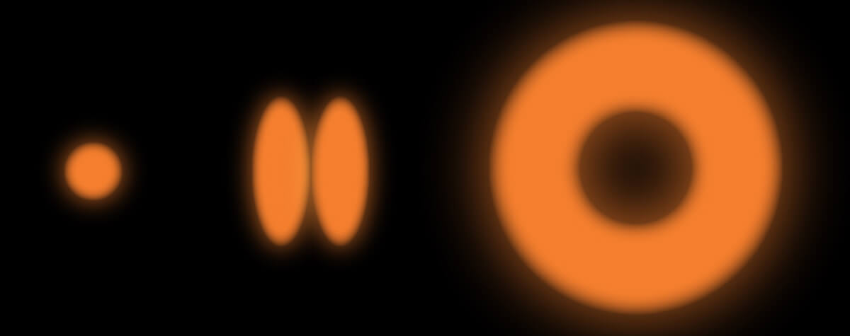
The spatial extent of the PSF, dictated by the finite wavelength of light, is the reason that a conventional confocal microscope is referred to as “diffraction-limited”. In a Stimulated Emission Depletion (STED) microscope, an additional laser is focused into the sample along with the excitation beam. This STED laser suppresses fluorescence via stimulated emission. Specifically, by means of its special donut-shaped PSF, it selectively keeps molecules that are off-center in a non-fluorescent state, allowing only those to fluoresce that are in the zero-intensity central region of the donut. This way, fluorescence is confined to a much smaller region than without STED i.e. the diffraction limit is broken and super-resolution is achieved (read more on how STED works here).
The sample, part of the optical path
The diffraction limit dictates the smallest possible size of an excitation PSF in an ideal situation. In practice, imperfections in the optical train, from the laser sources, up to and including the sample, and back to the detectors, compromise the imaging properties of the microscope and deform its otherwise diffraction-limited PSF. The sample is of special consideration. While imperfections in the optics are static, and therefore easily measured and corrected, inhomogeneities in the specimen are unpredictable and vary from sample to sample and even within a single imaging field of view1, 2. These imperfections and inhomogeneities give rise to optical aberrations, which – if left uncorrected – cause the excitation PSF of the microscope to become more diffuse, compromising the system’s resolution and excitation efficiency. Additionally, fluorescence that would otherwise be perfectly focused at the pinhole, becomes smeared out and can be blocked by the pinhole, leading to inefficient detection.
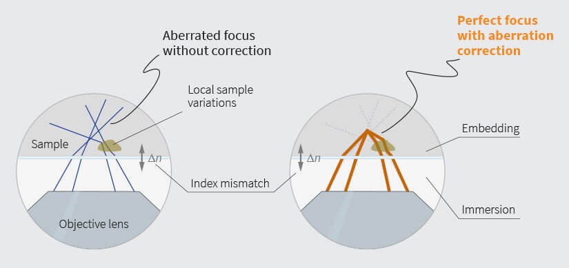
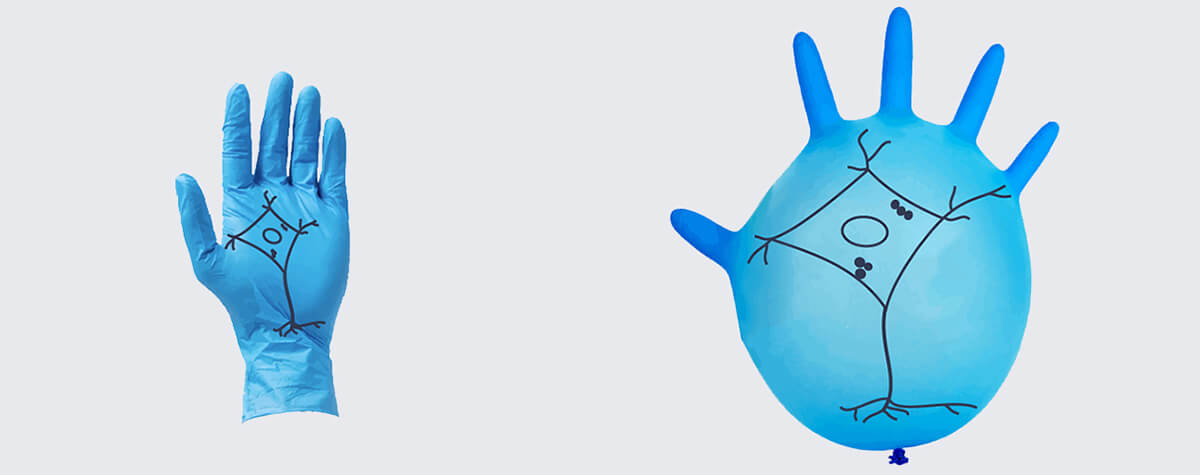
Fig.1 Left: an index mismatch between sample embedding and immersion medium causes rays to get bent away from the nominal focus. Local sample variations can have similar effects. Right: Using a deformable mirror to pre-bent all rays the right way before they enter the objective lens effectively cancels any negative effects.
Super-resolution microscopes have especially high demands for optical perfection. In a STED microscope, the main concern is the PSF of the STED laser. If the STED beam picks up aberrations on its way to the focal plane, the center of the STED-PSF will have a finite, non-zero intensity. This aberrated STED-PSF will then de-excite fluorescence entirely, rather than just confine it to the center of the ring, thus resulting in heavy losses in signal and resolution.
The problem is especially evident with three-dimensional-(3D-)STED. While the zero-intensity center of the two-dimensional STED doughnut is somewhat robust against aberrations, the center of the 3D-STED PSF quickly becomes non-zero even if only minor aberrations are present 3, 4.
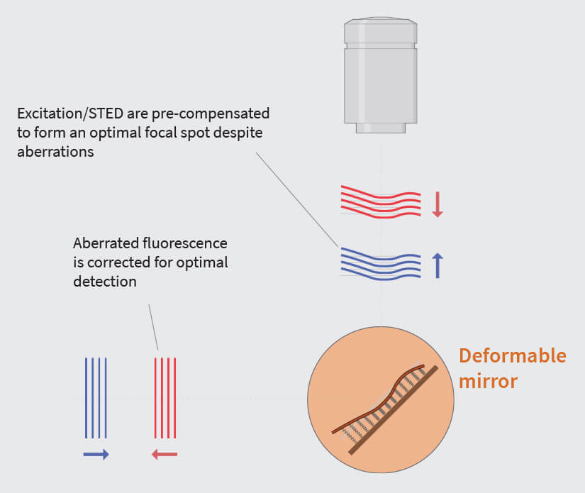
Fig.2 Variations of the refractive index in the sample can distort the wavefronts, leading to an imperfect focus. The prime reason, which is almost always present to some extent, is a refractive index mismatch between sample embedding and the immersion medium, although local variations in the sample can lead to aberrations, too.
Using a deformable mirror allows to effectively cancel aberrations. Deformable mirrors are adaptive elements with a reflective surface whose shape can be controlled. By applying the correct mirror shape, which is a negative of the distortions introduced by the sample, the focus is brought back to perfect shape, increasing signal and resolution even deep inside tissue.
Getting close is not good enough
A major source of aberrations in microscopy are regions in the sample with non-uniform refractive index numbers. When light encounters a change in refractive index, the rays are bent and continue to travel in a different direction, a phenomenon known as refraction. While designing lenses, refraction is a desired effect and manufacturers take great care in optimizing refraction so that lenses produce perfect (i.e. diffraction-limited) PSFs. Unfortunately, subsequent arbitrary changes in refractive index along a microscope’s optical beam path compromise this precise focusing ability.
One of the most prominent causes of an unwanted change in refractive index is the interface between the coverslip and the embedding medium of the sample, where an index mismatch can cause spherical aberrations and defocus (Fig. 1). Defocus changes the apparent focusing depth and can cause distance measurements along the z-axis to yield wrong results, while spherical aberrations give rise to a non-optimal PSF shape with characteristic long tails and multiple maxima.
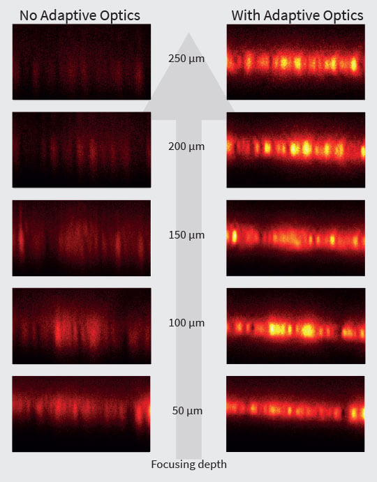
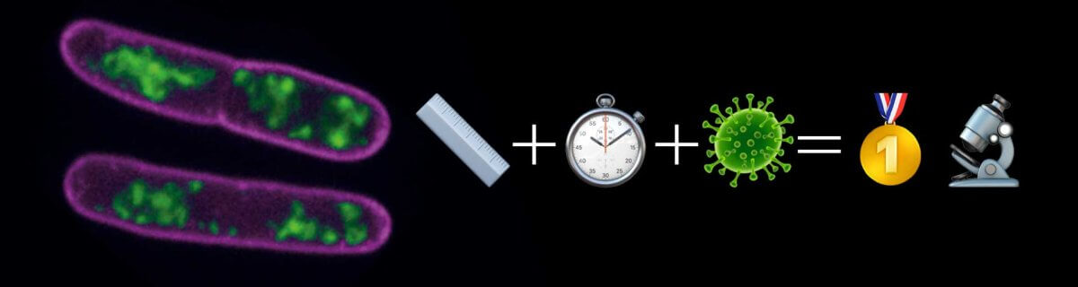
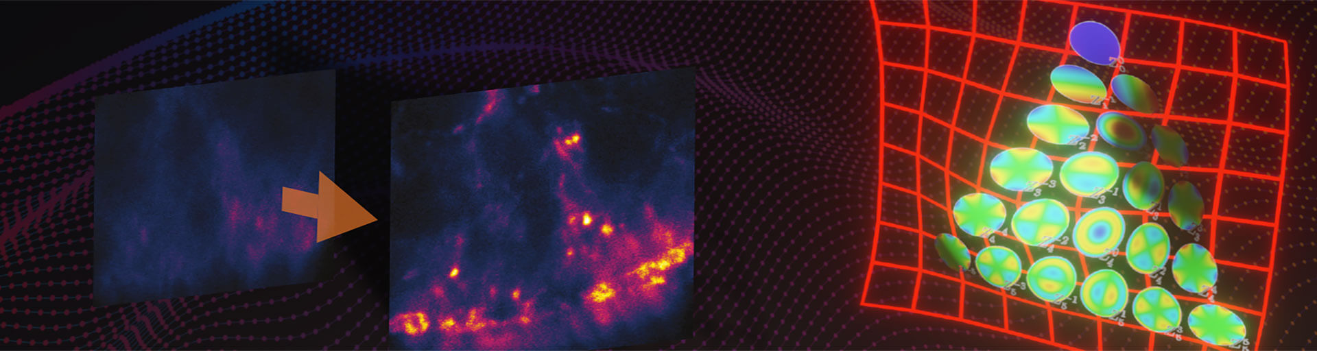
Fig. 3 Layer of fluorescent beads under index-mismatched conditions (left column) and corrected with abberior’s adaptive optics module, RAYSHAPE aberration correction (right). Note how brightness and resolution decrease with focusing depth when no correction is applied. All images are scaled to the same brightness.
Modern, high-NA oil objective lenses are designed to take into account the coverslip-immersion medium interface. However, the refractive index (nOIL = 1.518 at 23°C) is assumed to be constant after that, i.e. in the sample. Thus, embedding in Mowiol with a refractive index of 1.40–1.49 will cause aberrations and yet, this is still one of the best mounting medium recommendations for an oil immersion objective, second to embedding the sample in TDE 11, which is not always an option, e.g. for live-cell experiments. Similarly, the reason water immersion objectives lenses exist is that they closely match the refractive index required for live-cell work, and similar arguments hold for glycerol and silicone oil immersion lenses. Nevertheless, despite the close match between these immersion media and the specimens for which they were intended, “close” is often not good enough, and even a slight mismatch can give rise to aberrations.
An additional cause of aberrations are refractive index inhomogeneities in the specimen itself, for example transitions between lipid- or DNA-enriched regions and the rest of the cell. Most aberrations become more severe when focusing deep into a sample, such as thick tissue. This is the reason why multiphoton microscopy typically profits from aberration correction as well.
Optical aberrations and their effects on PSF shapes can be approximated using Zernike polynomials 5 to model the corresponding deformation of the wavefronts 1. The different orders of the polynomials are assigned to known optical aberration modes such that any arbitrary aberration shape can be easily described by decomposing it mathematically into its constituent Zernike modes.
Perfectly focused
Optical aberrations can be corrected via the implementation of adaptive optics. Before the STED and excitation beams enter the objective lens, they are “pre-aberrated” by an adaptive element that induces the same amount of aberration as the sample, but in the opposite direction. Consequently, when the pre-aberrated beams pass through the aberrating sample, the two sets of aberrations – the first induced the adaptive element and the second by the sample – cancel each other out. Furthermore, the emitted fluorescence, which also gets aberrated as it passes through the sample, is corrected by the adaptive element, too. This way, diffraction-limited conditions are restored at the focus and at the detection pinhole (Fig.2).
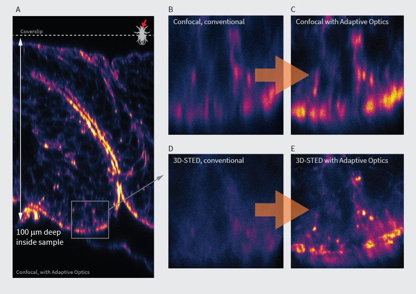
Fig.3 Confocal (B, C) and 3D-STED (D, E) images in deep tissue with (C, E) and without (D, B) abberior’s adaptive optics module, RAYSHAPE aberration correction. At focusing depths around 100 μm, confocal microscopy still gives a bit of signal (B), although it can be improved (C). However, 3D-STED at these depths is not possible (D) without RAYSHAPE, which restores brightness and resolution (E). Sample: inverted front half of L3-stage Drosophila melanogaster larva (A). Staining of Actin (Phalloidin-ATTO 647N). As the image is recorded, the aberration-compensating deformable mirror automatically follows the focusing depth. Once set up, acquisition runs completely automatic for bright, highresolution imaging at any depth. Samples by Sebastian Schnorrenberg, EMBL, Heidelberg.
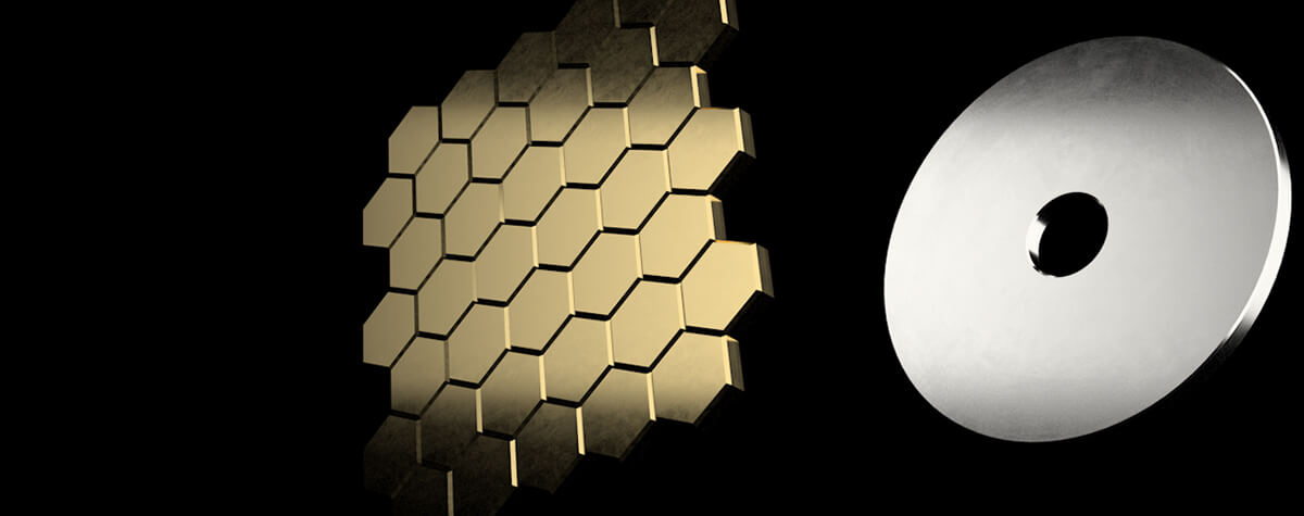
Reliable and systematic correction is made possible by the integration of adaptive optical elements such as deformable mirrors into the beam path. Deformable mirrors are coated membranes with a reflective surface whose shape can be controlled by actuators behind the membrane. The aberration compensation is achieved by applying the correct mirror shape, which is half the negative of the distortions introduced by the sample. It’s half the sample distortions, because the rays pick up one half on their way to the mirror and the other half on their way back. A suitable deformable mirror must have extremely high reflectivity from the ultraviolet to the infrared range to avoid losses, and enough actuators (more than 100) so that complex aberrations can be accurately rendered on its surface. Moreover, the response time of deformable mirrors must be sufficiently fast (down to ten milliseconds) so that corrections can be made dynamically within a single image acquisition. When implementing deformable mirrors into a microscope setup, great care must be taken to ensure that the surface shape exactly matches the desired deformation. This involves intricate calibration procedures 6 that take into account membrane stiffness, actuator coupling, actuator response and drift, etc.
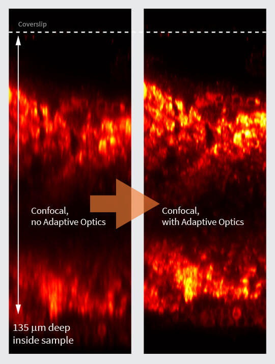
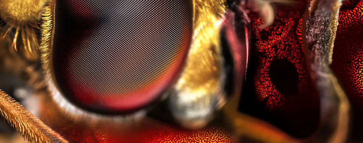
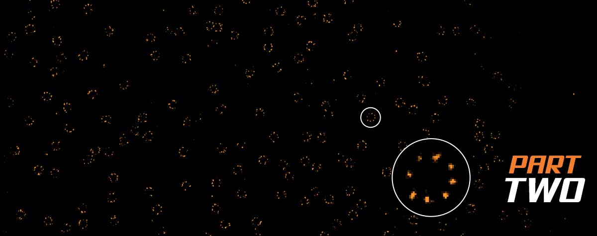
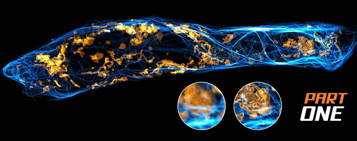
Fig.4 abberior’s RAYSHAPE aberration correction preserves resolution and brightness deep inside thick samples and enables imaging at low light levels (sample: bee brain cleared, courtesy of Amelie Cabirol and Albrecht Haase, University of Trento).
Deformable mirrors offer several advantages over objective correction collars. For example, deformable mirrors can correct arbitrary aberrations while correction collars can only correct for spherical aberration. In fact, certain aberrations, e.g. sample tilt 7, have been shown to compromise the effect of correction collars such that adjusting them makes the resulting image worse rather than better. In addition, deformable mirrors offer much faster response times and thus can be adjusted even between the lines of an image scan. They also have much longer lifetimes due to their non-mechanical nature, and they do not introduce moving parts into the beam path that can cause additional aberrations. Note, that movements of the mirror actuators are miniscule (< 1 µm) compared to movements of lens groups in an objective lens (mm).
Put into practice
Correction of the wavefront distortions has the potential greatly increase signal and resolution. As a rule of thumb, a greater refractive index mismatch, an increased imaging depth and a demand for more (super-) resolution all warrant the use of adaptive optics. While one can get away without aberration correction for confocal imaging close to the cover slip or in a sample embedded in Mowiol using an oil lens, imaging experiments in thick (> 100 μm) samples (Fig. 3, 4) or 3D-STED experiments at just a few microns below the sample surface 8, will not yield usable results and call for the use of adaptive optics.
To determine the exact amount of correction to apply on an adaptive optics system, several algorithms have been proposed 9, 10. Luckily, the most prominent type of aberrations, those caused by a refractive index mismatch, can be predicted using only focusing depth and the amount of refractive index difference. These aberrations increase linearly with depth and can be easily corrected as the sample is refocused, or during a volume or xz-scan, once the user has established them for a certain focusing position. This way, the imaging brightness of fluorescent beads at an imaging depth of 250 μm can be improved by up to a factor of five (Fig.3).
Performing a 3D-STED experiment 100 μm deep inside a complex sample such as Drosophila larvae inevitably requires adaptive optics. In this scenario, the severely aberrated PSF of the STED beam de-excites spontaneous fluorescence everywhere, leaving no useful signal and certainly no resolution. Here, using good adaptive optics makes all the difference between being able to get results or none at all.
References
1 M. Schwertner, M. Booth, and T. Wilson, “Characterizing specimen induced aberrations for high NA adaptive optical microscopy,” Opt Express 12, 6540-6552 (2004).
2 M. Schwertner, M. J. Booth, M. A. A. Neil, and T. Wilson, “Measurement of specimen-induced aberrations of biological samples using phase stepping interferometry,” Journal of Microscopy
(Oxford) 213, 11-19 (2004).
3 T. J. Gould, D. Burke, J. Bewersdorf, and M. J. Booth, “Adaptive optics enables 3D STED microscopy in aberrating specimens,” Opt Express 20, 20998-21009 (2012).
4 S. Deng, L. Liu, Y. Cheng, R. Li, and Z. Xu, “Effects of primary aberrations on the fluorescence depletion patterns of STED microscopy”, Opt Express 18, 1657-1666 (2010).
5 V. N. Mahajan, “Zernike circle polynomials and optical aberrations of systems with circular pupils,” Appl Opt 33, 8121 (1994).
6 M. Booth, T. Wilson, H. B. Sun, T. Ota, and S. Kawata, “Methods for the characterization of deformable membrane mirrors,” Appl Opt 44, 5131-5139 (2005).
7 R. Turcotte, Y. Liang, and N. Ji, “Adaptive optical versus spherical aberration corrections for in vivo brain imaging,” Biomed Opt Express 8, 3891-3902 (2017).
8 J. Heine, et al. “Three dimensional live-cell STED microscopy at increased depth using a water immersion objective.” Review of Scientific Instruments 89.5 (2018): 053701.
9 M. Booth, D. Andrade, D. Burke, B. Patton, and M. Zurauskas, “Aberrations and adaptive optics in super-resolution microscopy,” Microscopy 64, 251-261 (2015).
10 M. J. Booth, “Adaptive optical microscopy: the ongoing quest for a perfect image,” Light-Sci Appl 3, e165 (2014).
11 Staudt, Thorsten, et al. “2, 2′‐thiodiethanol: a new water soluble mounting medium for high resolution optical microscopy.” Microscopy research and technique 70.1 (2007): 1-9.